
by Daniel Pierre III, JN Machinery Corp.
On-line stress relieving of spring offers benefits, but not all furnaces are equal.
On-Line stress relieving was basically started by the Japanese in the early 1970’s. It was a process aimed to streamline production and greatly improve technology. The concept moved to the USA in the late 70’s using conveyor furnaces imported from Japan (Gasden Ro). Today, fast-cycle/high- temperature on-line stress relieving is the preferred method used by spring makers. JN Machinery was the first USA manufacturer to build on-line furnaces starting in 1982 and has over 2500 furnaces operating in spring plants throughout the world. The benefits of on-line stress relieving are as follows:
- No labor required to move parts to a separate heat treating area and no labor cost for the actual stress relieving.
- Lower operating cost with furnaces sized to the capacity of the production equipment.
- Immediate feedback on loads and dimensions.
- Improved quality.
In batch heating, parts are in baskets or containers and are constrained and shielded by the mass of surrounding parts. In addition, multilayer baskets are placed in thebatch furnace further shielding the inner located partsfrom airflow.
In on-line stress relieving, parts go through the furnace inlight layers. The parts get up to temperature faster thanwith batch heating, and all the parts receive the same amount of heat. As a result, load and dimensional variations are substantially reduced.
An example of improved quality of on-line stressrelieving with a JN-100 furnace verses batch heating canbe seen in Figure 1. This illustrates a 26% reduction on 6-Sigma variation when the JN-100 on-line furnace is used instead of a batch furnace.
Furnace Temperature Profile
An on-line furnace is a conveyor furnace with open ends.As a result, every point in the furnace is at a different temperature. lf you put thermocouples along the length of the belt line and left them there you would have a temperature profile similar to Figure 2. However, this is not the profile that the parts will experience.Setting the temperature of the furnace at 500°F(260°C) does not mean the parts will be heated to 500°F(260°C);it only means that the thermocouple reads 500°F(260°C) at that specific point in the furnace.
In order to know the temperature at which parts should be run, you must know the temperature profile of the furnace for various cycle times. The temperature profile the parts will see will be different for each time cycle.
Without a time/temperature profile you are in “never neverland” trying to guess what temperature to use. Most furnace manufactures do not supply time/temperaturecharts for two reasons:
- The furnace manufacturer does not understand spring manufacturing and how the temperature will affect dimensional characteristics.
- The furnace manufacturer will not take the time or effort to do a profile, which could easily take over100 hours.
JN Machinerysupplies time/temperature charts with every furnace it sells. A typical chart can be seen in Figure3.
Chartsare established by running product throughthe furnace with a thermocouple at a set temperatureand time cycle. Figure 3 shows the temperature profile based on different temperature set points for the same cycletime.
Use of Charts
Let’s say that a coiler producing 5000pph is connected with a JN-300 model furnace and the desired temperature is 500°F (260°C). Adjusting the belt speed for even distribution of parts over the belt results in a cycle time of five minutes. Go to Figure 3, whichis a five-minute cycle chart. Find the desired 500°F (260°C) temperature you want (vertical axis) andmove across the chart to determine set point temperature of the furnace. A rule of thumb is to have parts at or above the desired temperature for one-third the cycle time. In this case, a set point temperature of approximately 600°F (315°C) will produceparts operating on a five minute cycle time at 500°F (260°C) for at least one-third the cycle. Without a time/temperature chart, determining temperature would have been guesswork.
Another value of temperature profiles is evaluatingfurnaces from different manufacturers. Figure 4 shows a temperature profile of a JN-12 furnace compared to an imported furnace. Both furnaces are approximatelythe same size, but the JN furnace has 35% less wattage input which would lead you think that the JN model has less capacity or is less efficient getting product up to temperature . However, the time/temperaturecurve shows just the opposite – with the JN furnace gets product up to temperature faster and more uniformly. This is due to fan speed, heat shield and insulation – all of whichis covered in the Equipment Parameters section of this article.
Assurance of Adequate Stress Relief
The age old question in heat treating (referring to the above example), is, “How do I know springs heated at 600°F(315°C)on a five-minute cycle are adequately stress relieved and equal to a batch heat of 500°F(260°C) for 30 minutes?” Aside from usingtime consuming and costly analysis such as grain structure, x-ray defraction, spectral diffusionand fatigue testing, probably the simplest way is to perform a load loss test on the fast cycle/high temperature parts and compare the results with parts heated in the batch method.
If the load loss is equal to or less than the batch-heated parts, you should have confidence the on-line parts are adequately stress relieved.
Several technical reports have been written by IST (Institute of Spring Technology) and the Japan Society for Spring Research (JSSR) about on-line stress relieving with conclusions that high temperature, fast cycle stress relieving is equal to conventional stress relieving at temperature for long cycles. Additionally , the abundanceof on-line furnaces being used today should give credence that this method is now the industry standard.
Limitation of On-Line Heating
On-line heating is based on fast cycles and high temperatures, and does not lenditself to long cycle times used for precipitation hardening material like 17-7. Normallythe spring maker is using 17-7 condition C as drawn material. After fabrication , the parts are heated at 900°F( 480°C) for one hour. This is not a stress relief, but a hardening operation to achieve case hardening.
During the 900°F( 480°C), one-hourcycle, the parts are precipitation hardened- the yield strength of the material is increased approximately 25%.
A typical yield/time curve can be seen in Figure 5 on the next page. You will noticethat 60% of the transformation takes place in the first 15 minutes at 900°F(482°C). However, full transformation takes one hour and over aging will cause some loss of maximum yield strength.
If parts were heated in a conveyor furnace for one hour at 900°F( 480°C) they would be subject to the temperature curve shown in Figure 6 on the next page. Note that parts are not getting up to temperature until half way through the cycle and are losing temperature as the parts near the exit due to the open-end furnace construction. As a result, full transformation (hardening) has not been obtained.
A secondary effect is that during the one-hour cycle, a furnace with a tight mesh belt is basically stationary. Therefore,the belt is being cooked, and can it can become distorted.
Certification of Equipment:
As stated earlier, on-line furnaces are open ended and each point in the furnace is at a different temperature. The only things that can be certified as correct and within specification are the temperature controller, thermocouple and temperature at the location of the thermocouple. Trying to certify temperature at any other point in the furnace is meaningless.
Some customers want hard data on the temperature being run. This can easily be achieved with chart recorders and data collectors operating off the furnace thermocouple.
Equipment Parameters:
When evaluating and selecting on-line furnaces, there are several parameters to consider, as follows:
Elements – Tubular heaters are used in most of the online furnaces. The sheath materialand watt density/in² of surface area with adequate airflow determine the lifeof the elements. To cut cost, many manufacturers will use stainless sheaths and high-watt density elements which reduces the total number of elements required. However , this also contributes to short element life. We use Incoloy sheaths which can carry temperatures of l 700°F(926°C) and we limit the watt density to 25 w/in² for maximum element life.
Heat chamber – Basically two types of chamber construction are used. Most furnaces use insulated block chambers, which do an excellent job in insulating the furnace, but do not provide reflective ability insidethe chamber and absorb some of the airflow from the circulating fans.
We use a stainless chamber backed by ceramic fiber insulation . This not only allows better radiation from the heatingelements, but also provides a nonporous surface to maximize airflow from the circulating fans.
Fan speed – We believe in operating fans at high rpm to maximize airflow in the chamber, which gets product up to temperature faster.In some cases, JN is operating fans at 50% higher rpm than competition. Large furnaces , with high wattage input, should not have fans directly connected to the fan motor, as this will shorten fan motor life. The high chamber temperature will travel up the fan shaft into the motor. All JN furnaces over 12,000 watts have indirect driven fans which prevent heat from getting to the motor. Indirect driven fans also allows adjustment in rpm to balance airflow uniformity with capacity.
Belts – The material used in belts is usually 304 stainless steel, but 316 stainless steel (SS) does offer some improved resistance to high temperature distortion. We use 316 SS on our high capacity furnaces that heat from both above and below the belt.
The belt weave is either compound balance weave for tight construction that minimizes mesh opening, or balance weave that allows airflow through the belt. Many smaller furnaces use a compound balance weave that has a turned up edge to prevent parts from being trapped between the belt edge and the side rail of the conveyor.While the turned up belt edge works fine it hasseveral disadvantages when compared with a flat edge belt:
- It is 20 to 25% more expensive than a flat belt.
- More difficult to assemble.
- Cannot be turned over to minimize wear and offset cross bar camber.
One solution to prevent product from being trapped between the flat belt edge and the side rail is to use a side seal spring which is like a screen door spring that is attached to each end of the side rail and rests on the beltedge. This is a simple inexpensive solution that works 80 to 85% of the time.
Small wire diameter torsion springs sometimes present a problem by having their legs catch in the belt weave. If the operating temperature of the furnace is below 600°F(315°C), a silicone sealant (Dow Corning RTV 736) can be applied to the top surface of the belt which fills in the belt weave openings and provides a smooth solid surface for the springs.
Another method used for small springs is a tray furnace in which the belt has been replaced with trays that are connected to a chain that moves the trays through the furnace. JN offers two sizes of these.
Drive systems – Most on-line furnaces use a parallelshaft DC motor located below the drive drum and use chain and sprocket drive systems. This system presents severaldisadvantages:
- The location of the motor presents a problem, collecting product at the drop end. A deflection chute is usually required to get product away from the motor.
- The DC motor usually has commutator brushes that require replacement.
- Torque on motors is sometimes gear limited with the gearsmade from phenolic or die cast material.
JN Machinery has recently changedto AC motors with 100% hardened steel helical gearing. On all furnaces with belt widths l 2″(304 mm) and smaller, 90° direct drive AC motors are used with hypoid/helical gearing which is 80% more efficientthan worm gears.
Auxiliary operations
Many springs require color-coding which, in the past, has been done with solvent-based paintsand dyes in mixers, tumblers or sprayers, These methods are not only labor intensive, but also incursafety and EPA issues. JN Machinery ‘s TRC (temper, rustproof and coat) paint system uses the heat from the stress relieving process with a water-based polymer to providea color coating on the spring. See Figure 7.
Springs drop off the furnace belt into a polymer tank and are removed with an incline belt onto a drying conveyor. No labor is required, and the water-based polymer presents no EPA problems. The cost of the polymer is usually less than other solvent-dye finishes.
In conclusion, as high productivity and low pricingincreasingly become the determining factorswhether company A or B gets the order, it only makessense to utilize on-line stress relieving and a company like JN Machinery with over 40 years of spring experience, as a strategic part of your spring making process. For more information contact the author.
Conveyorized Furnace vs Batch Furnace
26% REDUCTION ON 6 SIGMA VARIATION

Figure 1-Spring Quality

Figure 2 – On-line furnace temperature

Figure 3 – Time/temperature chart for JN-300

Figure 4 – Temperature profile comparison

Figure 5 – Yield/time curve for 17-7 material

Figure 6 – Temperature curve for 17-7 material
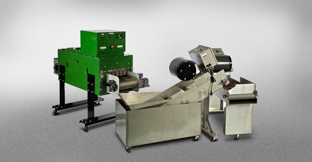
Figure 7 – JN Furnace with TRC Paint System